Preventing an Arc-tastrophe
Arc flash. It’s just two words and it can happen in a only few rapid moments. But it can cause extensive harm, painful consequences, and irreplaceable damage. An arc flash is the result of an arcing fault between electrical conductor(s) and another electrical conductor(s) or ground with enough electrical energy.
Arc flash. It’s just two words and it can happen in a only few rapid moments. But it can cause extensive harm, painful consequences, and irreplaceable damage.
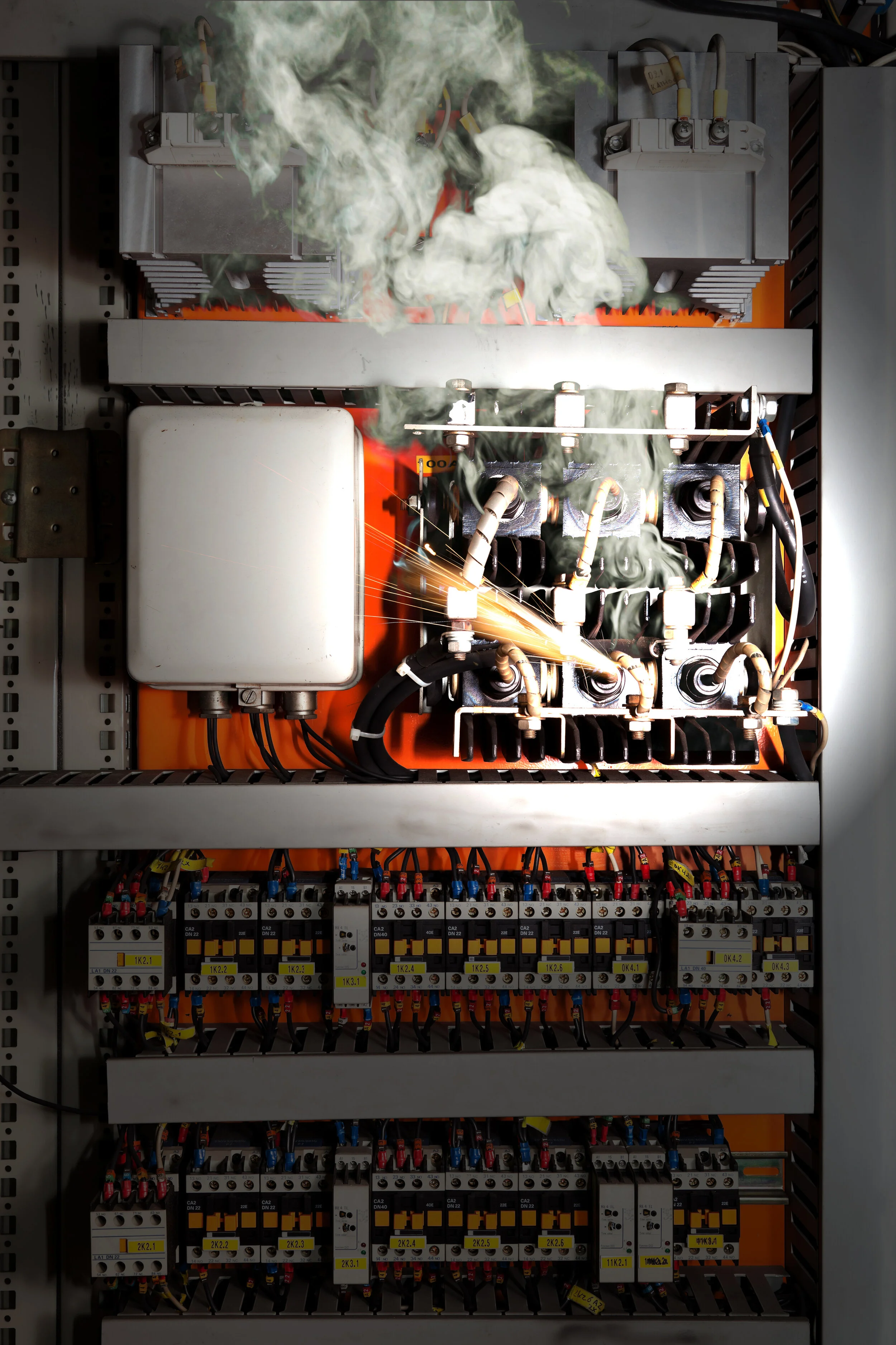
An arc flash is the result of an arcing fault between electrical conductor(s) and another electrical conductor(s) or ground with enough electrical energy. The fault gives off a rapid release of energy (light and heat). Air becomes the conductor. A massive amount of energy discharges during the arc flash or blast. This energy burns the conductors, vaporizing the copper and thus causing an explosive volumetric increase, the arc blast. This explosion propels deadly shrapnel and molten metal as it dissipates. This rapid release of energy can cause debilitating burns, other injuries and even death. But, It’s preventable. Spontaneous arc faults can stem from malfunctioning electrical equipment, improper precautions, negligent maintenance, or even unfitting electrical design.
Prevention: Hazard Analysis & Study

Employers and facility owners know that investing in the safety of their people, and their property is always worth it. A Hazard Analysis can identify areas in which preventative measures should be taken, where modifications should be made, and where risk factors become serious dangers. Among the hazard analysis and study include: Short Circuity Study, Protective Device Evaluation, and Protective Device Time Current Coordination Study.
Short Circuit Study:
The study calculates the maximum short circuit current the electrical power system may be subjected to at each equipment location through out the distribution network from the sources such as utilities, generators, and motors. The equipment includes substations, switchgear, motor control centers, and panels with their respective over current protective devices; generators; transforms; motors; and UPS equipment. The short circuit results determine the required ratings for electrical equipment to adequately sustain the fault current capacity of the system. If a short circuit occurs, the electrical power system’s available energy is directed to the point of the fault in amounts that greatly exceed the normal operating currents, and the equipment must have the ability to withstand and interrupt these large currents until the protective device opens to clear the faulted portion of the circuit.
Protective Device Evaluation:
This evaluation determines if the equipment ratings needed to sustain the fault currents calculated by the Short Circuit Study are adequate. Each circuit breaker, bus, etc., is reviewed in regards to the available short circuit to determine that the equipment can adequately withstand the fault current.
Protective Device Time Current Coordination Study:
The study reviews the relay and circuit breaker trip settings, fuses, and their operating time and current characteristics in order to properly coordinate these settings with upstream and downstream devices so that any faults are isolated to the location of the fault; hence, limiting the impact to the remaining portions of the system. The coordination study is used in an Arc Flash study to determine the length of time an arc would occur which is directly related to the incident energy associated with an arc flash event.
The Hazard Analysis will identify the locations which require PPE greater than Category 0. The review determines if there are possible arc flash mitigation recommendations that can be implemented to reduce the incident energy levels. Such recommendations might include device setting changes, replacement of molded case type circuit breakers with static trip type circuit breakers, changing fuse types, or installation of additional fused disconnects or circuit breakers. As a result of reducing the incident energy levels, the corresponding Category of PPE required to work on the equipment while energized is reduced.
Prevention: Take Action

In addition to addressing your hazard analysis, you should continue to make proper maintenance, training, and care a priority. Always complete regular maintenance on your equipment. Use proper signage and labeling where necessary. Provide your teams with proper safety equipment– like appropriate arc flash suits and fire resistant attire as well as PPE gear. And lastly, don’t forget to make arc flash training a part of your facility safety plan. It’s not enough just to have the information- make sure you do something with it too.
Know your codes:
The National Fire Protection Association Guidelines (NFPA 70E - Standard for Electrical Safety in the Workplace) provides direction to require facility owners to perform an arc flash risk assessment prior to allowing a worker or contractor to perform a task on energized equipment. The arc flash risk assessment identifies the presence and location of potential hazards and provides recommendations for PPE, boundaries for limited and restricted approaches, recommendations for flash protection, and safe work practices. NFPA 70E, ARTICLE 130.5 says an arc flash assessment must be completed to determine if an arc flash hazard exists, taking into consideration the design of the overcurrent protective device, its opening time, and its condition of maintenance. The assessment must be updated if a major modification or renovation takes place, and it must be reviewed periodically, at intervals not to exceed 5 years.
#ProblemSolved: Our Electrical Engineering team is here to help. Send an email to Seth Nace, PE, LC, LEED AP, Manager of Electrical Engineering at seth.nace@ssmgroup.com, or Emerick Martin, PE, Technical Manager of Electrical Engineering at emerick.martin@ssmgroup.com
Preventing an Arc-tastrophe
Arc flash. It’s just two words and it can happen in a only few rapid moments. But it can cause extensive harm, painful consequences, and irreplaceable damage. An arc flash is the result of an arcing fault between electrical conductor(s) and another electrical conductor(s) or ground with enough electrical energy.
Arc flash. It’s just two words and it can happen in a only few rapid moments. But it can cause extensive harm, painful consequences, and irreplaceable damage.
An arc flash is the result of an arcing fault between electrical conductor(s) and another electrical conductor(s) or ground with enough electrical energy. The fault gives off a rapid release of energy (light and heat). Air becomes the conductor. A massive amount of energy discharges during the arc flash or blast. This energy burns the conductors, vaporizing the copper and thus causing an explosive volumetric increase, the arc blast. This explosion propels deadly shrapnel and molten metal as it dissipates. This rapid release of energy can cause debilitating burns, other injuries and even death. But, It’s preventable. Spontaneous arc faults can stem from malfunctioning electrical equipment, improper precautions, negligent maintenance, or even unfitting electrical design.
Prevention: Hazard Analysis & Study
Employers and facility owners know that investing in the safety of their people, and their property is always worth it. A Hazard Analysis can identify areas in which preventative measures should be taken, where modifications should be made, and where risk factors become serious dangers.
Among the hazard analysis and study include: Short Circuity Study, Protective Device Evaluation, and Protective Device Time Current Coordination Study.
· Short Circuit Study - The study calculates the maximum short circuit current the electrical power system may be subjected to at each equipment location through out the distribution network from the sources such as utilities, generators, and motors. The equipment includes substations, switchgear, motor control centers, and panels with their respective over current protective devices; generators; transforms; motors; and UPS equipment. The short circuit results determine the required ratings for electrical equipment to adequately sustain the fault current capacity of the system. If a short circuit occurs, the electrical power system’s available energy is directed to the point of the fault in amounts that greatly exceed the normal operating currents, and the equipment must have the ability to withstand and interrupt these large currents until the protective device opens to clear the faulted portion of the circuit.
· Protective Device Evaluation - This evaluation determines if the equipment ratings needed to sustain the fault currents calculated by the Short Circuit Study are adequate. Each circuit breaker, bus, etc., is reviewed in regards to the available short circuit to determine that the equipment can adequately withstand the fault current.
· Protective Device Time Current Coordination Study - The study reviews the relay and circuit breaker trip settings, fuses, and their operating time and current characteristics in order to properly coordinate these settings with upstream and downstream devices so that any faults are isolated to the location of the fault; hence, limiting the impact to the remaining portions of the system. The coordination study is used in an Arc Flash study to determine the length of time an arc would occur which is directly related to the incident energy associated with an arc flash event.
The Hazard Analysis will identify the locations which require PPE greater than Category 0. The review determines if there are possible arc flash mitigation recommendations that can be implemented to reduce the incident energy levels. Such recommendations might include device setting changes, replacement of molded case type circuit breakers with static trip type circuit breakers, changing fuse types, or installation of additional fused disconnects or circuit breakers. As a result of reducing the incident energy levels, the corresponding Category of PPE required to work on the equipment while energized is reduced.
Prevention: Take Action
In addition to addressing your hazard analysis, you should continue to make proper maintenance, training, and care a priority. Always complete regular maintenance on your equipment. Use proper signage and labeling where necessary. Provide your teams with proper safety equipment– like appropriate arc flash suits and fire resistant attire as well as PPE gear. And lastly, don’t forget to make arc flash training a part of your facility safety plan. It’s not enough just to have the information- make sure you do something with it too.
#ProblemSolved: Our Electrical Engineering team is here to help. Send an email to Emerick Martin, PE, Senior Engineer at emerick.martin@ssmgroup.com or Seth Nace, PE, LC, LEED AP, Senior Engineer at seth.nace@ssmgroup.com
High-Definition Laser Scanning to Measure Floor Flatness
High definition laser scanning offers the best precision, efficiency, and accuracy to the process of measuring floor flatness. With speed unlike manual measurement, and collection of millions of points, digital scans identify and distinguish exactly where floors stand- competitively outshining historical practices.
Getting to the Bottom of It

Construction supervisors, contractors, architects, building developers, facility managers, inspectors, engineers, and other key stakeholders in facility and building construction all know well the critical concern that is floor flatness. Exact flatness in concrete floors is critical to efficient facility functioning, maximum floor tolerance, maintaining operations, and successful architectural design.
Down to minute measurements, 1/16th of an inch, floors that are not exceptionally flat cause major disruptions to existing facilities, or halt construction of new ones.
For industrial facilities- machinery, forklifts, handling equipment, and vertical storage all require precise concrete floor flatness. Lack thereof can increase chance of injury, loss of product, and damage to large equipment. Although rarely noticeable to an untrained eye, the impacts of a floor that is not flat are impossible to ignore.
For architects as well, modern designs require a similar preciseness. For example, glass walls and other popular design elements are all at the mercy of the flatness of the floor they will be placed on.
Rehabilitating and revitalizing existing structures also have a need for measuring floor flatness. Of primary concern among these are the settling of concrete over time. To successfully redevelop an existing facility, identifying the floor’s flatness is critical to successful tolerance and utility.
It is clear that measuring the precise flatness of a floor is of utmost priority to building development teams. But the priority is not new. Experienced teams are well-versed in the role and impact this priority has on timeline and long-term successfulness of building projects.
Although a historical concern, innovative teams are frequently searching for a better way. These teams are privy to the role that precision, efficiency, and accuracy all play in bringing construction projects to fruition. Because just measuring the floor’s flatness isn’t enough. The measurements should be precise. They should be done efficiently. And, the results should be accurate.
High definition laser scanning offers the best precision, efficiency, and accuracy to the process of measuring floor flatness. With speed unlike manual measurement, and collection of millions of points, digital scans identify and distinguish exactly where floors stand- competitively outshining historical practices.
Cutting-Edge Practices and Technology
Throughout the years, measuring to calculate F numbers (flatness) has taken a variety of methods. It wasn’t too long ago that technicians would lay a 10-foot straightedge on finished floor, identifying gaps and using these to calculate flatness. More recently, crews are deployed to walk slabs of concrete, take a variety of measurements, and generate a resulting calculation.
Both of these avenues leave great room for human error. In some instances, the straightedge method even presents discrepancies from technician to technician. In a similar regard, both of these tactics offer extensive manual labor, inhibiting work timelines.
In construction, time and value are often seen as contradicting. Developers are frequently forced to accept that accurate, precise results go hand in hand with extended timelines. In considering the value of precise floor measurements, it would be assumed that the process must be long to be accurate. But with 3D scanning, neither time nor accuracy must be sacrificed.
Laser scanning for floor flatness dramatically improves the three core areas of concern: precision, efficiency, and accuracy.
Here’s how it works:
Our survey and data collection technicians deploy cutting-edge scanners to the construction site. In just a few minutes, the floor space is scanned, collecting over thousands of single points that together form a digital rendition of the space at precise measurements.
This is repeated a number of times, each time utilizing the same control or benchmark within the space. Multiple scans of the same space is a practice that increases accuracy. Utilizing the benchmark ensures precision among each scan. The scans are transferred to digital format, creating a 3D point cloud- all of the multiple scans, millions of individual points, layered on top of one another, and anchored by the control.
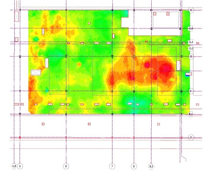
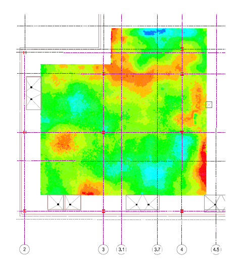
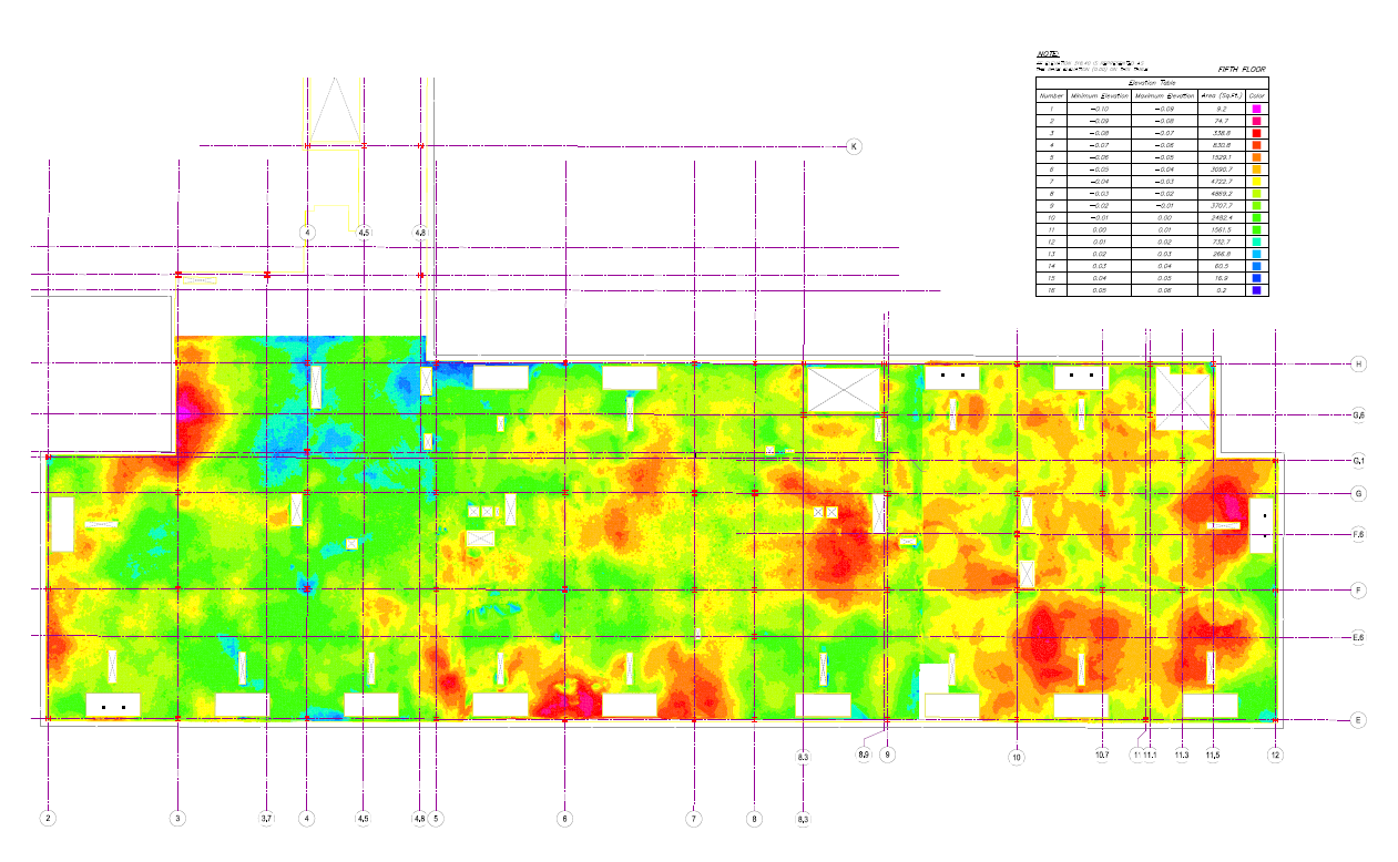
Digital scans of a space offer elevation information- identifying clearly the floor’s flatness. But scanning technology also offers the capability to calculate F numbers just as manual labor aims to do. Therefore, the technology reaches the desired conclusion in a better way, a faster way, and a more effective way.
Precision. Efficiency. Accuracy.

By collecting millions of points in minimal periods of time, laser scanning outshines manual labor and calculations. Technological advances decrease the opportunity for human error, and decrease the amount of time it takes to collect more information. And, this technology means not only more data, but more capabilities with that data.
21st century facilities shouldn’t be built with last century tactics.
We know that investing in cutting-edge technology and implementing cutting-edge practices changes the game for our clients. The outcome is evident- high definition laser scanning is the best way to measure floor flatness with precision, efficiency, and accuracy.
Looking to talk more about using scanning to measure floor flatness? Our Survey team would be happy to help. Send us an email at information@ssmgroup.com
#ProblemSolved: Read more about Survey and Data Capture.